
| Table of Contents |
| 1. Introduction 2. Sensors |
3. Microwaves |
| 4. Image Analysis 5. Applications |
Fundamentals of Remote Sensing
3.2 Radar Basics
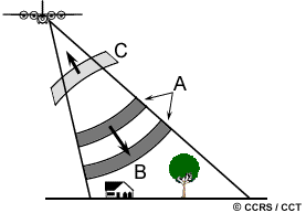 As noted in the previous section, a radar is essentially a ranging or distance measuring device. It consists fundamentally of a transmitter, a receiver, an antenna, and an electronics system to process and record the data. The transmitter generates successive short bursts (or pulses of microwave (A) at regular intervals which are focused by the antenna into a beam (B). The radar beam illuminates the surface obliquely at a right angle to the motion of the platform. The antenna receives a portion of the transmitted energy reflected (or backscattered) from various objects within the illuminated beam (C). By measuring the time delay between the transmission of a pulse and the reception of the backscattered "echo" from different targets, their distance from the radar and thus their location can be determined. As the sensor platform moves forward, recording and processing of the backscattered signals builds up a two-dimensional image of the surface.
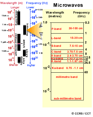
While we have characterized electromagnetic radiation in the visible and infrared portions of the spectrum primarily by wavelength, microwave portions of the spectrum are often referenced according to both wavelength and frequency. The microwave region of the spectrum is quite large, relative to the visible and infrared, and there are several wavelength ranges or bands commonly used which given code letters during World War II, and remain to this day.
- Ka, K, and Ku bands: very short wavelengths used in early airborne radar systems but uncommon today.
- X-band: used extensively on airborne systems for military reconnaissance and terrain mapping.
- C-band: common on many airborne research systems (CCRS Convair-580 and NASA AirSAR) and spaceborne systems (including
- ERS-1 and 2 and RADARSAT).
- S-band: used on board the Russian ALMAZ satellite.
- L-band: used onboard American SEASAT and Japanese JERS-1 satellites and NASA airborne system.
- P-band: longest radar wavelengths, used on NASA experimental airborne research system.
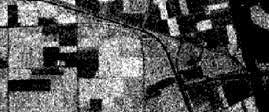
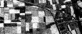
Two radar images of the same agricultural fields
Here are two radar images of the same agricultural fields, each image having been collected using a different radar band. The one on the top was acquired by a C-band radar and the one below was acquired by an L-band radar. You can clearly see that there are significant differences between the way the various fields and crops appear in each of the two images. This is due to the different ways in which the radar energy interacts with the fields and crops depending on the radar wavelength. We will learn more about this in later sections.
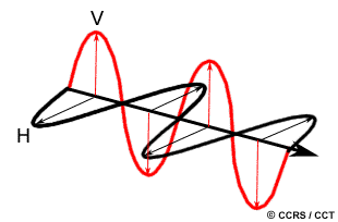 When discussing microwave energy, the polarization of the radiation is also important. Polarization refers to the orientation of the electric field (recall the definition of electromagnetic radiation from Chapter 1). Most radars are designed to transmit microwave radiation either horizontally polarized (H) or vertically polarized (V). Similarly, the antenna receives either the horizontally or vertically polarized backscattered energy, and some radars can receive both. These two polarization states are designated by the letters H for horizontal, and V, for vertical. Thus, there can be four combinations of both transmit and receive polarizations as follows:
- HH - for horizontal transmit and horizontal receive,
- VV - for vertical transmit and vertical receive,
- HV - for horizontal transmit and vertical receive, and
- VH - for vertical transmit and horizontal receive.
The first two polarization combinations are referred to as like-polarized because the transmit and receive polarizations are the same. The last two combinations are referred to as cross-polarized because the transmit and receive polarizations are opposite of one another. These C-band images of agricultural fields demonstrate the variations in radar response due to changes in polarization. The bottom two images are like-polarized (HH and VV, respectively), and the upper right image is cross-polarized (HV). The upper left image is the result of displaying each of the three different polarizations together, one through each of the primary colours (red, green, and blue). Similar to variations in wavelength, depending on the transmit and receive polarizations, the radiation will interact with and be backscattered differently from the surface. Both wavelength and polarization affect how a radar "sees" the surface. Therefore, radar imagery collected using different polarization and wavelength combinations may provide different and complementary information about the targets on the surface.

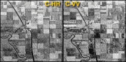
C-band images
![]()


![]()
| Updated 2002-11-27 | Important Notices |