
| Table of Contents |
| 1. Introduction 2. Sensors |
3. Microwaves |
| 4. Image Analysis 5. Applications |
Fundamentals of Remote Sensing
3.5 Target Interaction and Image Appearance
The brightness of features in a radar image is dependent on the portion of the transmitted energy that is returned back to the radar from targets on the surface. The magnitude or intensity of this backscattered energy is dependent on how the radar energy interacts with the surface, which is a function of several variables or parameters. These parameters include the particular characteristics of the radar system (frequency, polarization, viewing geometry, etc.) as well as the characteristics of the surface (landcover type, topography, relief, etc.). Because many of these characteristics are interrelated, it is impossible to separate out each of their individual contributions to the appearance of features in a radar image. Changes in the various parameters may have an impact on and affect the response of other parameters, which together will affect the amount of backscatter. Thus, the brightness of features in an image is usually a combination of several of these variables. However, for the purposes of our discussion, we can group these characteristics into three areas which fundamentally control radar energy/target interactions. They are:
- Surface roughness of the target
- Radar viewing and surface geometry relationship
- Moisture content and electrical properties of the target
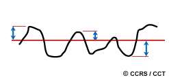
The surface roughness of a feature controls how the microwave energy interacts with that surface or target and is generally the dominant factor in determining the tones seen on a radar image. Surface roughness refers to the average height variations in the surface cover from a plane surface, and is measured on the order of centimetres. Whether a surface appears rough or smooth to a radar depends on the wavelength and incidence angle.
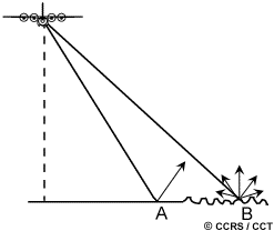 Simply put, a surface is considered "smooth" if the height variations are much smaller than the radar wavelength. When the surface height variations begin to approach the size of the wavelength, then the surface will appear "rough". Thus, a given surface will appear rougher as the wavelength becomes shorter and smoother as the wavelength becomes longer. A smooth surface (A) causes specular reflection of the incident energy (generally away from the sensor) and thus only a small amount of energy is returned to the radar. This results in smooth surfaces appearing as darker toned areas on an image. A rough surface (B) will scatter the energy approximately equally in all directions (i.e. diffusely) and a significant portion of the energy will be backscattered to the radar. Thus, rough surfaces will appear lighter in tone on an image. Incidence angle, in combination with wavelength, also plays a role in the apparent roughness of a surface. For a given surface and wavelength, the surface will appear smoother as the incidence angle increases. Thus, as we move farther across the swath, from near to far range, less energy would be returned to the sensor and the image would become increasingly darker in tone.
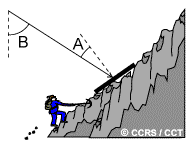 We have already discussed incidence or look angle in relation to viewing geometry and how changes in this angle affect the signal returned to the radar. However, in relation to surface geometry, and its effect on target interaction and image appearance, the local incidence angle is a more appropriate and relevant concept. The local incidence angle is the angle between the radar beam and a line perpendicular to the slope at the point of incidence (A). Thus, local incidence angle takes into account the local slope of the terrain in relation to the radar beam. With flat terrain, the local incidence angle is the same as the look angle (B) of the radar. For terrain with any type of relief, this is not the case. Generally, slopes facing towards the radar will have small local incidence angles, causing relatively strong backscattering to the sensor, which results in a bright-toned appearance in an image.
As the concept of local incidence angle demonstrates, the relationship between viewing geometry and the geometry of the surface features plays an important role in how the radar energy interacts with targets and their corresponding brightness on an image. Variations in viewing geometry will accentuate and enhance topography and relief in different ways, such that varying degrees of foreshortening, layover, and shadow (section 3.4) may occur depending on surface slope, orientation, and shape.
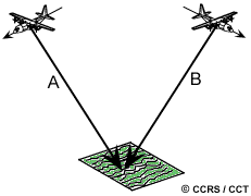
The look direction or aspect angle of the radar describes the orientation of the transmitted radar beam relative to the direction or alignment of linear features on the surface. The look direction can significantly influence the appearance of features on a radar image, particularly when ground features are organized in a linear structure (such as agricultural crops or mountain ranges). If the look direction is close to perpendicular to the orientation of the feature (A), then a large portion of the incident energy will be reflected back to the sensor and the feature will appear as a brighter tone. If the look direction is more oblique in relation to the feature orientation (B), then less energy will be returned to the radar and the feature will appear darker in tone. Look direction is important for enhancing the contrast between features in an image. It is particularly important to have the proper look direction in mountainous regions in order to minimize effects such as layover and shadowing. By acquiring imagery from different look directions, it may be possible to enhance identification of features with different orientations relative to the radar.
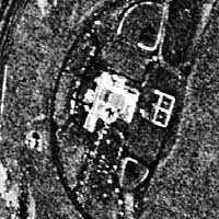
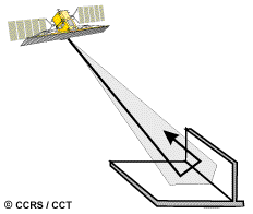 Features which have two (or more) surfaces (usually smooth) at right angles to one another, may cause corner reflection to occur if the 'corner' faces the general direction of the radar antenna. The orientation of the surfaces at right angles causes most of the radar energy to be reflected directly back to the antenna due to the double bounce (or more) reflection. Corner reflectors with complex angular shapes are common in urban environments (e.g. buildings and streets, bridges, other man-made structures). Naturally occurring corner reflectors may include severely folded rock and cliff faces or upright vegetation standing in water. In all cases, corner reflectors show up as very bright targets in an image, such as the buildings and other man-made structures in this radar image of a city.
The presence (or absence) of moisture affects the electrical properties of an object or medium. Changes in the electrical properties influence the absorption, transmission, and reflection of microwave energy. Thus, the moisture content will influence how targets and surfaces reflect energy from a radar and how they will appear on an image. Generally, reflectivity (and image brightness) increases with increased moisture content. For example, surfaces such as soil and vegetation cover will appear brighter when they are wet than when they are dry.
When a target is moist or wet, scattering from the topmost portion (surface scattering) is the dominant process taking place. The type of reflection (ranging from specular to diffuse) and the magnitude will depend on how rough the material appears to the radar. If the target is very dry and the surface appears smooth to the radar, the radar energy may be able to penetrate below the surface, whether that surface is discontinuous (e.g. forest canopy with leaves and branches), or a homogeneous surface (e.g. soil, sand, or ice). For a given surface, longer wavelengths are able to penetrate further than shorter wavelengths.
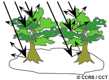
If the radar energy does manage to penetrate through the topmost surface, then volume scattering may occur. Volume scattering is the scattering of radar energy within a volume or medium, and usually consists of multiple bounces and reflections from different components within the volume. For example, in a forest, scattering may come from the leaf canopy at the tops of the trees, the leaves and branches further below, and the tree trunks and soil at the ground level. Volume scattering may serve to decrease or increase image brightness, depending on how much of the energy is scattered out of the volume and back to the radar.
| Updated 2002-11-27 | Important Notices |

