
| Table of Contents |
| 1. Introduction 2. Sensors |
3. Microwaves |
| 4. Image Analysis 5. Applications |
Fundamentals of Remote Sensing
3.7 Advanced Radar Applications
In addition to standard acquisition and use of radar data, there are three specific applications worth mentioning.
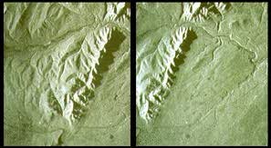
The first is stereo radar which is similar in concept to stereo mapping using aerial photography (described in section 2.7). Stereo radar image pairs are acquired covering the same area, but with different look/incidence angles (A), or opposite look directions (B). Unlike aerial photos where the displacement is radially outward from the nadir point directly below the camera, radar images show displacement only in the range direction. Stereo pairs taken from opposite look directions (i.e. one looking north and the other south) may show significant contrast and may be difficult to interpret visually or digitally. In mountainous terrain, this will be even more pronounced as shadowing on opposite sides of features will eliminate the stereo effect. Same side stereo imaging (A) has been used operationally for years to assist in interpretation for forestry and geology and also to generate topographic maps. The estimation of distance measurements and terrain height for topographic mapping from stereo radar data is called radargrammetry, and is analogous to photogrammetry carried out for similar purposes with aerial photographs.
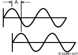
Radargrammetry is one method of estimating terrain height using radar. Another, more advanced method is called interferometry. Interferometry relies on being able to measure a property of electromagnetic waves called phase. Suppose we have two waves with the exact same wavelength and frequency traveling along in space, but the starting point of one is offset slightly from the other. 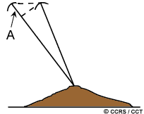 The offset between matching points on these two waves (A) is called the phase difference. Interferometric systems use two antennas, separated in the range dimension by a small distance, both recording the returns from each resolution cell. The two antennas can be on the same platform (as with some airborne SARs), or the data can be acquired from two different passes with the same sensor, such has been done with both airborne and satellite radars.
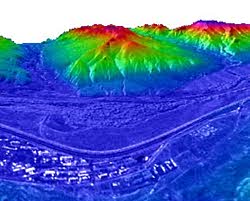
 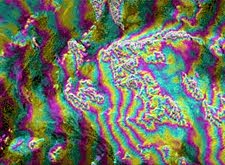 By measuring the exact phase difference between the two returns (A), the path length difference can be calculated to an accuracy that is on the order of the wavelength (i.e centimetres). Knowing the position of the antennas with respect to the Earth's surface, the position of the resolution cell, including its elevation, can be determined. The phase difference between adjacent resolution cells, is illustrated in this interferogram, where colours represents the variations in height. The information contained in an interferogram can be used to derive topographic information and produce three-dimensional imagery of terrain height.
The concept of radar polarimetry was already alluded to in our discussion of radar fundamentals in section 3.2. As its name implies, polarimetry involves discriminating between the polarizations that a radar system is able to transmit and receive. Most radars transmit microwave radiation in either horizontal (H) or vertical (V) polarization, and similarly, receive the backscattered signal at only one of these polarizations. Multi-polarization radars are able to transmit either H or V polarization and receive both the like- and cross-polarized returns (e.g. HH and HV or VV and VH, where the first letter stands for the polarization transmitted and the second letter the polarization received). Polarimetric radars are able to transmit and receive both horizontal and vertical polarizations. Thus, they are able to receive and process all four combinations of these polarizations: HH, HV, VH, and VV. Each of these "polarization channels" have varying sensitivities to different surface characteristics and properties. Thus, the availability of multi-polarization data helps to improve the identification of, and the discrimination between features. In addition to recording the magnitude (i.e. the strength) of the returned signal for each polarization, most polarimetric radars are also able to record the phase information of the returned signals. This can be used to further characterize the polarimetric "signature" of different surface features.
![]()

![]()
| Updated 2002-11-27 | Important Notices |