
| Table of Contents |
| 1. Introduction 2. Sensors |
3. Microwaves
|
| 4. Image Analysis 5. Applications |
Fundamentals of Remote Sensing
3.3 Viewing Geometry and Spatial Resolution
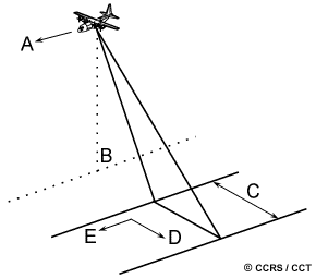 The imaging geometry of a radar system is different from the framing and scanning systems commonly employed for optical remote sensing described in Chapter 2. Similar to optical systems, the platform travels forward in the flight direction (A) with the nadir (B) directly beneath the platform. The microwave beam is transmitted obliquely at right angles to the direction of flight illuminating a swath (C) which is offset from nadir. Range (D) refers to the across-track dimension perpendicular to the flight direction, while azimuth (E) refers to the along-track dimension parallel to the flight direction. This side-looking viewing geometry is typical of imaging radar systems (airborne or spaceborne).
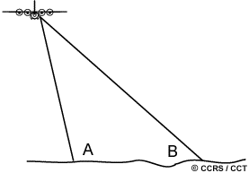
Near range
The portion of the image swath closest to the nadir track of the radar platform is called the near range (A) while the portion of the swath farthest from the nadir is called the far range (B).
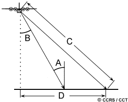
Incidence angle
The incidence angle is the angle between the radar beam and ground surface (A) which increases, moving across the swath from near to far range. The look angle (B) is the angle at which the radar "looks" at the surface. In the near range, the viewing geometry may be referred to as being steep, relative to the far range, where the viewing geometry is shallow. At all ranges the radar antenna measures the radial line of sight distance between the radar and each target on the surface. This is the slant range distance (C). The ground range distance (D) is the true horizontal distance along the ground corresponding to each point measured in slant range.
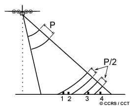 Unlike optical systems, a radar's spatial resolution is a function of the specific properties of the microwave radiation and geometrical effects. If a Real Aperture Radar (RAR) is used for image formation (as in Side-Looking Airborne Radar) a single transmit pulse and the backscattered signal are used to form the image. In this case, the resolution is dependent on the effective length of the pulse in the slant range direction and on the width of the illumination in the azimuth direction. The range or across-track resolution is dependent on the length of the pulse (P). Two distinct targets on the surface will be resolved in the range dimension if their separation is greater than half the pulse length. For example, targets 1 and 2 will not be separable while targets 3 and 4 will. Slant range resolution remains constant, independent of range. However, when projected into ground range coordinates, the resolution in ground range will be dependent of the incidence angle. Thus, for fixed slant range resolution, the ground range resolution will decrease with increasing range.
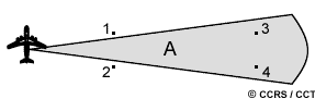
The azimuth or along-track resolution is determined by the angular width of the radiated microwave beam and the slant range distance. This beamwidth (A) is a measure of the width of the illumination pattern. As the radar illumination propagates to increasing distance from the sensor, the azimuth resolution increases (becomes coarser). In this illustration, targets 1 and 2 in the near range would be separable, but targets 3 and 4 at further range would not. The radar beamwidth is inversely proportional to the antenna length (also referred to as the aperture) which means that a longer antenna (or aperture) will produce a narrower beam and finer resolution.
Finer range resolution can be achieved by using a shorter pulse length, which can be done within certain engineering design restrictions. Finer azimuth resolution can be achieved by increasing the antenna length. However, the actual length of the antenna is limited by what can be carried on an airborne or spaceborne platform. For airborne radars, antennas are usually limited to one to two metres; for satellites they can be 10 to 15 metres in length. To overcome this size limitation, the forward motion of the platform and special recording and processing of the backscattered echoes are used to simulate a very long antenna and thus increase azimuth resolution.
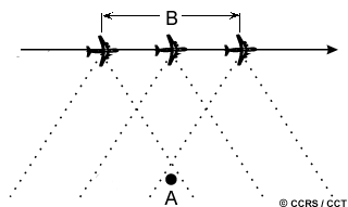
This figure illustrates how this is achieved. As a target (A) first enters the radar beam (1), the backscattered echoes from each transmitted pulse begin to be recorded. As the platform continues to move forward, all echoes from the target for each pulse are recorded during the entire time that the target is within the beam. The point at which the target leaves the view of the radar beam (2) some time later, determines the length of the simulated or synthesized antenna (B). Targets at far range, where the beam is widest will be illuminated for a longer period of time than objects at near range. The expanding beamwidth, combined with the increased time a target is within the beam as ground range increases, balance each other, such that the resolution remains constant across the entire swath. This method of achieving uniform, fine azimuth resolution across the entire imaging swath is called synthetic aperture radar, or SAR. Most airborne and spaceborne radars employ this type of radar.
![]()

![]()
| Updated 2002-11-27 | Important Notices |